Feed Rate (Milling)

The tool's travel distance during a single spindle revolution is referred to as the feed rate. It is referred to as the cutter feeding speed. It is expressed in terms of turning distance per revolution.

Considerations for Feed Rate in CNC Machining:

Machinists consider the following factors while determining the workpiece's optimal value:

  • Type of the Tool: The kind of tool used to cut the material is largely dependent on the kind of material being fed into it. As a result, the tool needs to be appropriate for the material being fed.
  • Surface Finishing of the Work Piece: As feed rate rises, surface roughness also rises. The feed rate is therefore decreased to provide a clean surface finish.
  • Cut Width: The chip may narrow if the cut width is less than half the diameter. This results in production flaws. The feed rate needs to be raised to alleviate this problem.
  • Use of TPI: Threads per inch, or TPI, are inversely proportional to feed rate. The range of thread pitch of the screws being used determines the feed rate.

Feed Rate Formulas

Where:

Vf : Table Feed [mm/min or Inch/min]

Fn : Feed per revolution [mm/rev or Inch/rev]

Fz : Feed per Tooth [mm/tooth or Inch/tooth]

n: Spindle Speed [RPM]

How To Calculate the Milling Feed Rate from The Basic Data?

Calculating Feed Rate:

Feed Rate = RPM x N x CL

Definitions:
  • RPM = Revolutions Per Minute, Spindle Speed, Number of revolutions of spindle per minute
  • SFM = Imperial. Surface Feet Per minute, Cutting speed, Speed at which tip of tool travels through material
  • SMM = Metric. Surface Meters Per minute, Cutting speed, Speed at which tip of tool travels through material
  • Feed Rate = Inches Per Minute or Millimeters Per Minute, Feed Rate, Distance in inches or millimeters the tool will travel through workpiece per minute
  • N = Number of teeth on the cutter
  • CL= Chip Load per tooth, this is the advancement of the cutter per revolution per each cutting edge. Otherwise generally explained as the thickness of material each tooth takes per each revolution

With the mentioned parameters, you can proceed to determine the Milling Feed:

  • Determine the Feed per Tooth by multiplying the chip thinning variables.

According to the tool geometry and application settings, the Chip Thinning factors ensure that the actual Feed per Tooth [Fz] will retain the required Chip Load.
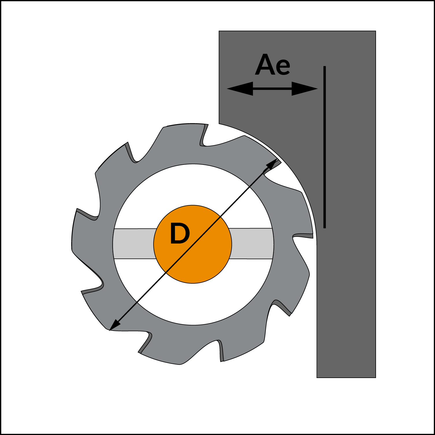
  • The Radial Chip Thinning Factor [RCTF] should be used when the Radial Depth of Cut [Ae] is less than the radius of the cutter. The factor is 1 (when Ae is larger). The factor can be up to three times at very small Ae.

Radial Chip Thinning factor calculation:


%
Where:

RCTF: Radial Chip Thinning Factor

WOC: Radial Width of Cut

D: Diameter of Cutter

RCTF small calculator

  • When the cutter does not have a typical 90° form, the approach angle chip thinning factor [ACTF] should be used (For example a Ballnose or Chamfaring cutter).

Chip Thinning factor for Chamfer/feed milling cutters:


%

ACFT small calculator

  • Based on the chip load and chip thinning variables, calculate the feed per tooth as follows:
  • Using the cutting speed and cutter diameter, determine the RPM:

(If your  Vc is in  m/min units use 1000 instead of 12 in the above formula)

  • Calculate the table feed in the final stage: