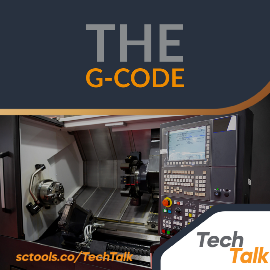
“When your excuses try to convince you to quit, remember why you started.” - Unknown
Understanding G-Codes for CNC
G-codes and CNC (Computerized Numerical Control) are two different types of programming that machines use to create a shape. In its most simplistic terms, G-codes are sets of instructions that program a machine to create a shape but require a true beginning and endpoint to work correctly. On the other hand, CNC codes are created by a computer to create different shapes without much precision.
The G-codes are commands that provide a range of motion and control functions, depending on the tool being used and the system running it. The G-codes also identify what tool is being used, along with the axis of rotation, travel limits, and electrical system voltages.
The G-Code Language Explained
The G-code is produced as the output of CAD/CAM (computer-aided design/computer-aided manufacturing) software. The machine is instructed to perform a sequence of instructions executed by just using a code to achieve the desired shape, such as changing positions, speeds, rotations, etc.
The formation of shapes is achieved by stringing together sets of instructions one at a time. These components must operate flawlessly together to achieve a specific goal, which often necessitates hundreds or thousands of lines of code.
In G-code, points are represented as lines, and line-by-line instructions are used to create a part. This means that the same part can be created in various ways, each with its own set of features.
G Commands
In G commands, the machine is prepared to move one way or another. In addition to the instructions, the machine usually gives coordinates to know where to move. The program also provides "safety" settings for the CNC machine to be set up correctly during start-up.
G-Code
A G-code is a preparatory code that begins with the letter G, and it indicates what action the machine tool should perform, for example:
- Rapid move (Transfer the tool through space to where it needs to be used and in a quick movement)
- Alternate coordinate systems in G50-G53
- Workpieces are cut and routed to a specific dimension, or a profile (contour) shape is added to an edge of a workpiece by controlled feed moves.
- The Controlled Speed (G04 CNC, for example) command stops the machine from doing anything for a specified amount of time.
- The work offset and length offset is set in the tool information.
- An mm/inch input system is used by G95 G code for interpreting feed commands as micrometers per revolution (mm/rev) or inches per revolution of the spindle.
The G-Code Codes List
While each machine tool manufacturer may adopt its G-Codes, a basic set of G-Codes is the same on every machine tool. Generally, these standards are used on CNC machines, such as Lathes and Mills.
Each kind of cutting tool has its code, and these codes follow a specific order that establishes a standard terminology, similar to Morse code in communication. An explanation of each code is given below, along with an overview of the milling process.
- G00 Positioning at rapid travel (Machine moves straight, milling, cutting, etc.).
- G01 Linear interpolation based on feeding rate - rapid motion
- G02 Circular interpolation clockwise - controlled motion
- G03 Circular interpolation with counterclockwise motion
- G04 Dwell
- G10 Set the working datum
- G17 Choose the X-Y plane
- G18 Choose the Z-X plane
- G19 Choose the Z-Y plane
- G20 Units of measurement
- G21 Measurements in metric
- G27 Check return of references
- G28 Automatically return to the reference point
- G29 Navigate to a location through a reference point
- G31 The skip function
- G32 Lathe operation to cut threads
- G33 Milling operation with thread cutting
- G40 Offset cutter compensation
- G41 Left compensation for cutter
- G42 Right compensation for cutters
- G43 Tool length compensation
- G44 Tool length compensation
- G50 Set mill coordinates and maximum rotation speed
- G52 Configuration of the local coordinate system
- G53 Machine coordinate system setting
- G54-G59 Set Datum
- G70 Finish cycle (Lathe)
- G71 Lathe rough turning cycle
- G72 Lathe rough facing cycle
- G73 Drilling cycle of chip breaks
- G74 Left-hand tapping machine
- G74 Cycle for face grooving
- G75 Drilling cycle for OD grooves (Lathe)
- G76 Cycle of boring
- G76 Screw cutting cycle (Lathe)
- G80 Cycles to cancel
- G81 Drill cycle
- G82 Drill cycle with dwell
- G83 Peck drilling cycle
- G84 Tapping cycle
- G85 Bore in and bore out
- G86 Bore in and rapid out
- G87 Back boring cycle
- G90 Programming in absolute
- G91 Programming incrementally
- G92 Reposition the origin point
- G92 A cycle in Screw thread cutting on Lathe
- G94 Minute-by-minute feed
- G95 feed per revolution
- G96 Surface speed control (lathe)
- G97 Constant surface speed cancel
- G98 Feed per minute (Lathe)
- G99 Feed Rate per Revolving (Lathe)
The CNC machines come pre-programmed with a set of functions for the user's convenience. The built-in program is referred to as a subprogram and is accessed by G-code commands. In machine instructions, pre-existing codes are described, and their functions are explained.
Numerically controlled (NC) machine tools had been around for a long time before G-Code programming. Over the years, and with a significant amount of effort, the G-Code has become the standard for the industry for all numerically controlled machine tools.
Meta Description: G-code is a plain text language used to direct CNC machines. Reading G-codes is essential to making CNC machines do what you need.

|
If you have any questions about carbide cutting tools, end mills, drills, etc. be sure to reach out to us @ sctools.co/Home or call us at (877)737-0987. We help you machine better! |


Comments (0)